Monday, June 7, 2010

Traynor YBA-2b BassMate Voiced for Guitar

This is a Traynor bass amp that a client brought to me with some minor complaints and some mods he wanted done.  This was the last YBA2b version and was produced in 1977-78 with two 12ax7a's for preamp and PI and two el84/6bq5's for output.  The combo houses a 15"
speaker.  Here's the link related to the mods he was looking for - pretty standard bass amp to guitar amp kind of thing... different coupling caps and some voice tweaking.

http://www.guitarscanada.com/amp-tech-section/7672-traynor-yba-2b-question-wild-wild-bill-3.html

His other complaint was it was sounding very thin, that it was all ear-piercing high-end with weak low-end... not good for a bass or guitar amp.  My first guess was a cap job was necessary - any 30 year old amp with original caps needs them replaced.  This will typically solve the loss of bass.

So it seemed like a pretty straight-forward recap/mod/re-voice but this amp by it's very nature presented some challenges and so was a lot more interesting to work on.

The amp was spec'd to work on 115VAC.  Today we have 120VAC and in reality (at least at my home) I see 123VAC from the wall.  This amp is already being run by design at the upper end of what a couple of EL84's can handle as far as B+ on plate and screen are concerned.  With the additional supply voltage this baby was running voltages that I thought  were excessive.  Tube life was probably pretty short for these poor old 84's but would need to be changed every few months if run the way it was.

I'll post soon and get into the particular mods that were done in re-voicing the amp and also how the elevated B+ voltage was handled.  Until then...

Wednesday, March 17, 2010

Been Gone Too Long

Wow, it's been a while since I've had the time to post any further - holidays came, business has picked up.  I did make a good deal of progress on the "Twin-Super" amp... still tweaking and will need to build some cabinetry.  I haven't decided on a combo or head configuration.  I continued taking pics until my camera bit the dust - I'll be posting the next few steps and then will have to skip ahead a bit while filling in some gaps.... coming soon.

Here's one of the amps I've been working on for clients:


A beautiful `65 Fender Princeton.  This thing was a true closet classic.  I really didn't have to do much other than check voltages and general operation, clean pots, re-tension tube sockets, check tubes, etc. as this client wanted to keep it all original.


Gut shot - very clean...  even though the amp functioned well, it needed a recap as the electrolytic filter caps are far beyond there intended lifespan.  The amp functioned properly but these caps are definitely not performing at 100% and will not be reliable.  Not an issue here as this one will not be a player - it is nearly a museum piece that will be kept original.


Checking the main filter caps for DC leakage.


I'll be posting about the latest amp I've been working on - a `77 Traynor YBA2b Bassmate... a very interesting piece of equipment that has brought a few weird problems with it.

Sunday, December 6, 2009

Twin-Super Amplifier Project - Preparing the Chassis Pt. 1


So the next step is preparing the chassis which consists of drilling (or punching) the holes and mounting the various components (sockets, pots, fuse holder, pilot lamp, etc.).

The first step is to take our drilling template and transfer drilling points.  This template looks pretty confusing, huh?


It actually isn't that complex - all those numbers are just the drill size/hole size.  We won't actually be making all these holes either - you can see around where the transformers will be mounted there are numerous holes to account for various size transformers.  Also, because of the preamp design I chose, I will not use all the holes for tubes.  I have 2 smaller holes for 12ax7 tubes (preamp and phase inverter), 2 6l6gc output tubes and 1 5ar4/gz34 rectifier tube (all the large holes with a black dot) and the two very small holes on either side which are for securing the sockets.  I'm waiting to drill holes for mounting the transformers as I am waiting for delivery from Edcor.  I know these transformers are different in the mounting than the Hammond transformers that this template indicates.  I'll update this when I have the PT and OT which should be in a few days.

What I do is cut small holes in the center of each tube hole on the template then press through that with a Sharpie and transfer onto the enclosure.

Then I use a punch to tap a small indentation into the enclosure.  This ensures that my drill bit will not wander when I start the hole. 

I use the same procedure for the front and back of the chassis.     


So now I have transferred all points where I'll need to drill (for now...) - let's do some drilling!

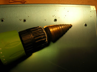
I use what are called stepped drill bits - these things are great.  There is also a trade name, Unibit.  You can get these in any Home Depot or the like.

This is a smaller step bit - it goes from like 1/8" to 1/2"... no more changing bits (although they really only work for thin surfaces - you're not going to be able to drill holes through a 2x4 piece of lumber but it's perfect for drilling holes in an aluminum enclosure).  I start with the smaller bit and drill pilot holes up to 1/2".


Then I switch to the big guns...   I got this set from Harbor Freight (lots of cheap tools, not the greatest quality but good for some things).  Here's a link Large Step Bits .  They are pretty cheap compared to the Irwin you see above.  That's okay because really, how many holes this big am I going to be drilling?  It is a slow process and I will warn you that there will be very sharp burrs left around the edges of the holes.  Another way do get holes like this is to use a punch such as this Punch .  They are not cheap however!  


Here's the result:


 In the next part I'll finish preparing the chassis...

Wednesday, November 25, 2009

Twin-Super Amplifier Project - Mounting Board Components

Next we move on to mounting and soldering components to the board.  Here's the layouts we are following:


The top is the power amp board and the bottom is the preamp board.  Mounting components is pretty straight forward - follow the diagram, insert component leads in the appropriate places and solder them in.

  Power Amp board without components    


Preamp board completed 


Keep in mind that certain components are polarized - that is they have a positive and a negative.  In this case, the large blue capacitors and the two smaller black caps need to go in the proper direction - they will be marked.
Solder all the components in as you go then when they are all in clip the excess leads off from the back.

One thing to note - there are usually connections to make on the backside of the board.  This board is no exception.  These connections are represented by the dashed lines on the layout.(see above)


And here they are...  also keep in mind that we will be making connections from these boards to transformers, tubes, etc.  Some would recommend we go ahead and place these leads on the board now, but I would rather wait and make the connections when I have all the chassis components mounted.  And so, that is our next step - preparing the chassis.


Sunday, November 15, 2009

Twin-Super Amplifier Project - Eyelet Boards

Our next step is to construct the boards many of the components will be mounted on - we call these "eyelet boards".  First, we need a template to transfer where we need to drill holes - these are available at the AX84
site.  Here's one:

First, I print them with no scaling (they are pdf's) to make sure they're the correct size. Then punch holes where necessary and use a sharpie to mark the actual board.  I ordered the board material and eyelets from
Watts Tube Audio .  It is available in many sizes - typically I use 1/16" thick 2.625" width or 2.875" width.
You need to order double the length you will need so a piece of blank board without holes can be used as an insulator placed behind the component board when it is mounted.

So I have transferred drill holes from the template with a Sharpie and drilled 1/8" holes... next I need to insert and set the eyelets.  The eyelets are small circular metal pieces that component leads will be mounted through and soldered to.  The eyelets are mounted with an eyelet staking tool.  This is sort of like a nail set or center punch.  I got mine from Watts here .  Make sure you get the eyelet staking tool.  There is another type of mounting hardware called a turret - I have never used them but they can be used just as an eyelet would.  The process is simple - place the eyelet in the hole, flip the board over and set it by hammering the tool into the back side of the eyelet.  I use a piece of wood to hammer on - if you stake on a hard surface the eyelet will be flattened out and we don't want that.  The back of the eyelet is expanded and drawn tight to the board.


Here is a photo of the staking process...


and the finished board.

Next up will be the process of mounting components to the finished board.... til then.... adieu.


Friday, November 13, 2009

Twin-Super Amplifier Project - Start

In the following blog series I will document the construction of a guitar amplifier. The first step was to choose and amp. I was looking for a 20W-25W push-pull configuration - something Fender-y - something like a Twin or Super, thus The Twin-Super is born.  I used the building blocks found on the DIY homebrew amp site AX84.com . They consist of a couple different power sections and maybe a half dozen preamp sections. The schematics, board templates and layouts are all on the site and are pretty good. I decided to go with a 20W push-pull power section and the "simple" preamp - I can always change this later on.

The first order of business was to order all the components. The site has BOM's (bill of material) for the various projects so it was pretty easy. I used Mouser Electronics , Hoffman Amps as my main suppliers for components. Both are excellent companies. For transformers I decided to go with Edcor . The two I chose were the CXPP25-MS-7.6K Push-Pull Output Transformer ($ 56.51) and the XPWR008 Power Transformer ($53.77). Their prices are reasonable, but, you can only order direct from them and it takes a month or more for the order to arrive - no big deal, there is plenty to do.

Here's some of the stuff I start with -  BOM, schematics, layouts, etc... all from AX84 and some parts I've received...


After all the components arrived it was time to get building...  first is to make the eyelet boards some of the components will be mounted on - but that is for the next installment...